(Still Under Construction)
written by Zhengyu Zhang
The objective of this project is to prototype a component-based behavior
simulation system using Java programming language. As the fundermental
element of such a simulation enviroment, a component is formed by
the encapsulation of the behavior of a functional block within a
digital system. The complete simulation process can be characterized as
the activities of many different components with every individual self-describing
the behavior subject to external input and initial condition and interchanging
input and output with each other. We believe this type of simulation system
is a more adaptive, more scalable, and more efficient way of performing
behavior simulation for digital systems with various complexities at all
abstraction levels.
There are two main applications for doing behavior simulation. The first is in the evalution of a new design. Information related to functional or logic correctness can be obtained from behavior simulation for high level specification or a VLSI circuit while breadboarding is impractical. A second application exists in the area of fault analysis. Here, the test engineer may desire information related to what faults are detected by a proposed test sequence or what is the operational characteristic of the circuit under specific fault conditions? These and other questions can be dealt with effectively by the process of fault simulation.
Traditionally, a behavior simulation system consists of the structural description of a functional block, the input data , the initial value of memory states and a simulator.The structual description might be at gate level, which consists of the topology of the circuit and the circuit element types, or at register transfer level, along with a list of primary inputs and primary outputs. A high level language is often used for describing input sequence, desired output format, etc. The simulator is a program that interprets all the inputs, applies the input data to the digital system and computes the outputs.
Event driven and native compiled mode are the most commonly used techniques to implement the simulator. When implemented using the event driven technique at gate level, the simulator is able to exploit the infrequency of logic switching in a digital circuit. Only the logic gates with changing inputs are processed. In this type of simulator, the names of the active logic gates are first placed inside a data structure called event list (scheduler) according to the chronology of the switching activities, then the simulation is carried out by processing the event list and performing the computation in the scheduled order. On the other hand, simulators implemented using native compiled mode technique is generated via mapping the structural description into platform-specific machine level instructions which is directly directly executable by RISC hardware. As the result, such a kind of simulation sometimes runs 2 to 25 times faster than the simulation based on event driven technique.
Compared with our new model, it is important to point out that , in a traditional simulation system, while the top level functional representation is usually hierarchical, the format at the lower level has mostly been flat. Designers may declare procedures for various types of building blocks; nonetheless, this hierachical structure is collapsed by the preprocessor where the information about each atomic element has to be referred to globally. For example, in the case of event driven logic simulator, the event list must keep the track of every single gate instead of the subcircuit.
As the complexity of the design increases, it is no longer the case that one person or even a small team of engineers can accommodate such a task. Nowadays, more designs are being done in a distributed fashion-that is-a design project is divided into many small pieces and each member in a design team works on one part of it. This indeed causes difficulties for the testing engineers who want to verify the whole design because different parts must be integrated first. Imagine what happens when one part of the design is updated. The whole simulator created for old version has to be discarded and a new simulator needs to be rebuilt. What if updates occur really often? Much time is wasted on setting up the simulation instead of actually doing it. Hence, a methodology adapable to fast changing design style will play a crucial role in the overall success of the design. Also, the simulation performance has long been an important issue: a formal simulation with billions of input vectors easily takes several week to finish and any small enhancement in the basic algorithm can achieve a significant amount of time-savings. Given the fact that there are numerous, heterogeneous computing resources distributed across the network, wouldn't it be nice to efficiently leverage them to improve the performance?
We claim that our new system offers inherent advantages in solving above problems over the traditional simulation systems. Our new model requires the designer to compile his own part of the design into a component: to debug his own design, the designer simply asks the component to simulate itself; after he notifies testing engineers of where the component resides, the test engineers integrate different components remotely by some network protocols and the whole simulation system is now up and running. If one designer updates his part of the design to a new version, he only needs to build a new component to replace the old one and the entire simulation system runs without any additional modifications-no new simulator has to be rebuilt. And this simplifies and helps proliferate the reuse of the previously designed components as well as the components from external sources. Furthermore, assume that every components possesses sufficient local processing power and the bandwidth of the network interconnection is reasonble enough, a multitude of synchronized self-simulating components can transform the network into a giant parallel multi-processor supercomputer! Finally, the full-fledged design can be wrapped into a super component and placed on the world wide web to make it available to third-party designers or potential OEMs. They will have the option to mix and match different components and run press-button simulation from any remote client machine, while the actual computation is totally done distributedly. This scenario fits right into the WELD's big picture.
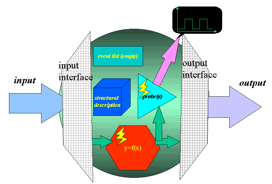
A fundermental component (Figure 1) is composed of a structural description, an event list and at least two methods: the probe method, which displays the wave form of the output, and the simulate method which descibes the behavior the component; it interacts with external world through the input and the output interface. The simulate method computes the output vectors after the component reads in inputs and initial state. Note that although the code inside the simulate method is mostly generated by mapping the component's own structural description into Java code, the behavior of the component no longer relates to the structural description once the component is compiled into byte code. In addition, it might seem redundant to include an event list in the compiled mode simulator; however, it will become clear later that this type of vertical consistency simplies the understanding of the structure of a higher level component.
The input/output interface is comprised of two parts: a protocol capable of communicating with other components residing either locally or across the network, and a tablelike data structure called buffer which temporarily stores the incoming/outgoing data. A buffer is especially beneficial to the performance of the simulation system where the transmission delay is nontrivial and the cycle-based approach is impractical.
Figure 1. The content of a fundermental component
A high level component is formed by wrapping together several lower level components (children). It has the same structure as its child: it has all the data type and methods that a fundermental component has and also communicates with the outside world via the input/output interface. It also accomplishes the same simulation task as a fundermental component does but uses a different mechanism. In the case of self-simulation, event-driven technique is employed. Namely,the whole computation is performed by asking each lower level component to simulate itself and drive another component in the next clock cycle, the scheduling of the process is pre-configured and stores in the event list. In Figure 2, there are five sub-components in a super-component. These five sub-components, with each submitting to the event list, are cascaded into a closed loop and the simulate method for the super-component, instead of being the mapping of the overall structral description, are merely function calls to invoke the simulate method in every sub-component. Very same approach is utilized by the probe method of a super-component. For this case, the probe method for the super-component simply requests the sub-components to pop out their own wave-from displays.
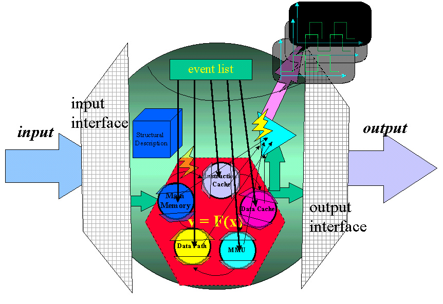
Figure 2. The abstract view of a higher-level component
If a user wants to simulate the entire system, he will need to interact with the top level component. The top level componenent will accept the inputs, then spread the inputs to the lower level components as well as request messages and scheduling messages. These lower level components receive their pieces of assignments and pass onto next lower levels. Eventually, the inputs will reach the fundermental components and it is the fundermental component that does the real simulation work, all other levels of components serve as messaging and controlling nodes. Figure 3 showes such a component based simulation system.
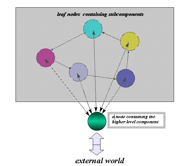
Figure 3. A small component based simulation system
In order to achieve performance gain for the component based simulation system, we will have to ensure the efficiency of the overall system as well as that of each single component. First, each fundermental component will possess enough local processing power. Second, each fundermental component should impose a properly demanding load to its local computing resource just enough to squeeze out maximum performance from it. Finally, the bandwidth of the interconnect link must be sufficient and stable to guarantee the global synchronization of all the components within the system.
Ideally, the perfomance scales linearly with the number of processors if component pipelining is realized. By component pipelineing we mean that multiple input vector or input vector set are overlapped: the work to be done in a pipeline for an input vector (set) is broken into small pieces, each of which takes a fraction of time needed to compute the final output. For example, in Intel's Paragon supercomputer, every processor has its own memory subsystem and OS; processors are interconnected via the ultra-high bandwidth fiber optical data links. Assume our simulation system is placed onto such a computer and we tune the system according to the requirements list above, every component will compute its current output vector at one clock cycle, then use it to drive a next stage components and compute the next output vector at the next clock cycle: at almost any particular moment, our system guarantees that no single processor is idle; thus, the efficiency of the overall system is maximized. And yes, our new model is a very natrual way of doing simulation in parallel.
In a practical system, we have to deal with various type of computers linked via different networks. With certain reasonable assumptions about all the resources available, it is still possible to improve the simulation performance to the largest extent. To tackle the problem of low bandwidth networks, we propose that a component first computes an input vector set instead of just one vectors a time with the size of such a set as a controlling parameter of the system. In the other word, a component should spend most of its time doing simulation instead of waiting for the next input set.
The synchronization problem is vital to the overall behavior of the system.
At java code level, the top level object is called Component object with default methods such as RUNME() and Probe() as well as default class variables like Event_list, I/O_Interface and Structure. I/O_Interface will be implemented as another class with its own set of methods and variables dealing with network protocols plus providing temporary data storage. Two types of subclass will exist as the subclass as Component object. One is called BasicObject that corresponds to the fundermental component. The other is called MasterObject that corresponds to the all other levels of components. The front end is proposed somewhere Digsim alike for now and is tentative.
The final goal is undetermined which could be a set of APIs or a Digsim type simulator although Iˇˇam seriously thinking about the some other possibilites such as a simple compiler to turn a piece of VHDL code into a network dispatchable, byte code level component or any combination of them.
1. For the first three months, some literature survey has been done. So far, we have found that all the related publications assume the traditional simulation system and most work has been done on the implementation of the old simulator, either by event driven or compiled mode technique.
2. Some experimental components has been created along with a waveform display panel.
By the end of 1996, a small scale component based simulation system is planned to be up and running with the assumption that all the component will stay on one machine. We might also show a demo as the final project for our EE244 project.