|

A Framework for Hardware-Software Co-Design of Embedded
Systems
Please send questions or comments to polis-questions@ic.eecs.berkeley.edu
Embedded controllers for reactive real-time applications are implemented as
mixed software-hardware systems. These controllers utilize Micro-processors,
Micro-controllers and Digital Signal Processors
but are neither used nor perceived as computers. Generally,
software is used for
features and flexibility, while hardware is used for performance. Some
examples of applications of embedded controllers are:
- Consumer Electronics: microwave ovens, cameras, compact disk players.
- Telecommunications: telephone switches, cellular phones.
- Automotive: engine controllers, anti-lock brake controllers.
- Plant Control: robots, plant monitors.
Design of embedded systems can be subject to many different types of
constraints, including timing, size, weight, power consumption, reliability,
and cost.
Current methods for designing embedded systems require to specify and
design hardware and software separately. A specification, often incomplete
and written in non-formal languages, is developed and sent to the hardware and
software engineers. Hardware-software partition is decided a priori
and is adhered to as much as is possible, because any changes in this
partition may
necessitate extensive redesign. Designers often strive to make everything
fit in software, and off-load only some parts of the design to hardware to
meet timing constraints. The problems with these design methods are:
- Lack of a unified hardware-software representation, which leads to
difficulties in verifying the entire system, and hence to
incompatibilities across the HW/SW boundary.
- A priori definition of partitions, which leads to sub-optimal
designs.
- Lack of a well-defined design flow, which
makes specification revision difficult,
and directly impacts time-to-market.
There are many different academic approaches to try to solve the problem of
embedded system design. In our opinion,
none of them address satisfactorily the issues of unbiased specification and
efficient automated synthesis for
control-intensive reactive real-time systems. Therefore, we are developing a
methodology for specification, automatic synthesis, and validation
of this sub-class of embedded systems (that includes
the examples described above).
Design is done in a unified framework, POLIS, with a unified
hardware-software representation, so as to prejudice neither hardware nor
software implementation. This model is maintained throughout the design
process, in order to preserve the formal properties of the design.
The POLIS system is centered around a single Finite State Machine-like
representation. A Co-design Finite State Machine (CFSM), like a classical
Finite State Machine, transforms a set of inputs into a set of outputs with
only a finite amount of internal state. The difference between the two models
is that the synchronous communication model of classical concurrent FSMs is
replaced in the CFSM model by a finite, non-zero, unbounded reaction time.
This model of computation can also be described as Globally Asynchronous,
Locally Synchronous.
Each element of a network of CFSMs describes a component of the system to be
modeled. The CFSM specification is a priori
unbiased towards a hardware or software
implementation. While both perform the same computation for each CFSM
transition, hardware and software
exhibit different delay characteristics. A synchronous hardware
implementation of CFSM can execute a transition in 1 clock cycle,
while a software implementation
will require more than 1 clock cycle.
CFSMs are also a synthesizable and verifiable model,
because many existing theories and tools for the FSM model
can be easily adapted for CFSM.
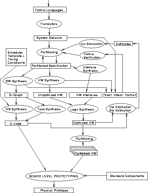
The design flow that is currently implemented in the POLIS
system is depicted in the following figure and is
described more in detail
below.

- High Level Language Translation
In POLIS, designers write their specifications in a high level
language (e.g., ESTEREL, graphical FSMs, subsets of Verilog or VHDL)
that can be directly translated into CFSMs. Any high level language with
precise semantics based on extended FSMs can be used to model individual
CFSMs (currently ESTEREL is supported directly).
- Formal Verification
The formal specification and synthesis methodology embedded within POLIS
makes it possible to interface directly with existing formal verification
algorithms that are based on FSMs. POLIS
includes a translator from the
CFSM to the FSM formalism which can be fed directly to verification systems
(e.g.
VIS).
In addition to uncovering bugs in a design, we also use formal verification to
guide the synthesis process. Since the abstract
CFSM model covers the behavior of all
possible hardware-software implementations at once, it is possible to refine
the specification base on the output of formal verification. Formal
verification tools today still have problems with complexity. We have
developed a methodology which incorporates a set of abstraction and assumption
rules specific to POLIS and CFSMs.
With this formal verification
methodology we are able to verify designs which are larger than is previously
possible.
- System Co-simulation
System level HW-SW Co-simulation is a way
to give designers feedback on their design choices. These design choices
include HW-SW partitioning, CPU selection, and scheduler selection.
Fast timed
co-simulation (up to millions of clock cycles per second on a workstation)
is possible in POLIS thanks to the
software synthesis and performance estimation techniques described below.
We currently utilize
PTOLEMY
as a simulation engine, but we are not limited to
PTOLEMY. VHDL code including all the
co-simulation information is also an output of
the system, so any commercial VHDL simulator can be adapted for this purpose.
- Design Partitioning
By design partitioning we mean making system-level design decisions such as
HW-SW partitioning, target architecture selection, and scheduler selection.
These decisions are based heavily on design experience and are very difficult
to automate. We therefore provide the designer with an environment to quickly
evaluate any such decision through various feedback mechanisms
from either formal verification or system co-simulation.
- Hardware Synthesis
A CFSM sub-network chosen for HW implementation is
implemented and optimized using logic synthesis techniques from
SIS.
Each CFSM, interpreted as a Register-Transfer Level specification, can be
mapped into BLIF, XNF, VHDL or Verilog.
- Software Synthesis
A CFSM sub-network chosen for SW implementation is mapped into a
software structure that includes a procedure for each CFSM, together
with a simple Real-time Operating System:
- CFSMs. The reactive behavior is synthesized in a two-step
process:
- Implement and optimize the desired behavior in a high-level,
processor-independent representation of the decision process similar
to a control/data flow graph.
- Translate the control/data flow graph into portable C code and use any
available compiler to implement and optimize it in a specific,
micro-controller-dependent instruction set.
A timing estimator quickly analyzes the program
and reports code size and speed
characteristics. The algorithm uses a formula, with parameters obtained from
benchmark programs, to compute
the delay of each node in the control/data flow
graph for various micro-controller architectures (characterization
data for MIPS R3000 and Motorola 68HC11 and 68332 are already
available). The precision of the estimator, with
respect to true cycle counting,
is currently on the order of plus or minus 20 percent.
The estimator allows one
to obtain accurate estimates of program execution times for
any characterized target processor, by first appending to each statement in
the C code generated from the control/data flow graph instructions that
accumulate clock cycles, then compiling and execute the software on the host
workstation. The same method is used to synchronize hardware and software
blocks within the PTOLEMY-based co-simulation environment.
- Real-time Operating System. An application-specific OS,
consisting of a scheduler (e.g. Rate-Monotonic and Deadline-Monotonic) and
I/O drivers, is generated for each partitioned design.
- Interfacing Implementation Domains
Interfaces between different implementation domains (hardware-software) are
automatically synthesized within POLIS. These interfaces come in the
form of cooperating circuits and software procedures (I/O drivers) embedded in
the synthesized implementation. Communication can be through I/O ports
available on the micro-controller, or general memory mapped I/O.
The following organizations have contributed to the development of the
POLIS system:
- University of California, Berkeley, CA
- Cadence Berkeley Labs of Cadence Design Systems Inc., Berkeley, CA
- Magneti Marelli, Torino and Pavia, I
- Politecnico di Torino, Torino, I
- Hitachi Ltd., Tokyo, JP
- Daimler Benz GMBH, Berlin, DE
- Centro Studi e Laboratori di Telecomunicazioni, Torino, I
- NEC C&C Research Labs, Princeton, NJ
POLIS Release 0.4
 UCB Design Technology Warehouse Homepage
|


 UCB Design Technology Warehouse Homepage