|
 |
ContentsMetropolis Home Download Overview Metamodel Tools Design Methodologies Platform-Based Design Wiki Publications 2/07 DVCon Paper 4/07 IEEE Article 4/03 IEEE Article 6/02 GSRC Presentations People Polis Search Members GSRC Metro Mail Embedded Metro Mail Wiki src Private Forum |
Metropolis Model Structure Viewer User's GuideContentsIntroductionThe Metropolis model structure viewer is an Eclipse plugin. It presents a graphical display of the objects in a Metropolis model and the connections between their ports.Below is an example of the display of the top-level netlist of the Picture-in-Picture modeling example. 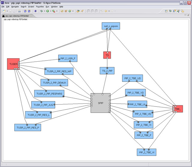
Double-clicking on an object representing a netlist (displayed as a gray box by default) opens another view showing the structure of that netlist. Double-clicking on another object opens a text editor on the source code for that object. RequirementsTo date, the Structure Viewer has been tested on Windows XP and Redhat Enterprise Linux Release 4.The Structure Viewer requires Eclipse 3.1 or later, using Java version 1.5 or later, and the Graphical Editor Framework (GEF) Eclipse plugin, release 3.1.1 or later. It also requires a local installation of Metropolis. Also, in order to do automatic layout, the open-source GraphViz layout programs from AT&T must be accessible. Installation
SetupBefore you can use the Metropolis plugin, some initial setup is necessary within Eclipse:
Creating a Metropolis ProjectIn order to create a graphical view of a Metropolis model, the model must be in a Metropolis project under Eclipse. Create a project from theFile menu:
You are first prompted to give the project a name. The name must be the name of the root package of your model. The top-level folder of the project is where you will put any metamodel (.mmm) source files belonging to the top-level package, and any subfolders containing sub-packages.
After entering the name, you can hit Source CodeYour Metropolis metamodel (.mmm) source code can be created in place using Eclipse's text editor, or it can be imported into your project.
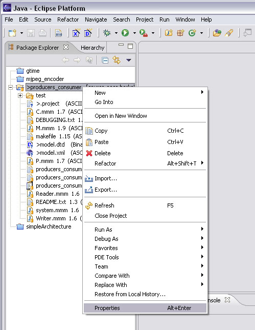
To import files that are accessable from your file system,
select the project title in the Package Explorer view,
right-click to bring up the context menu, and select the
"
If your files are in CVS, you can instead use the
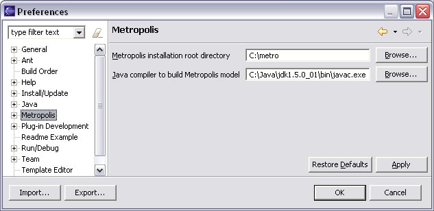
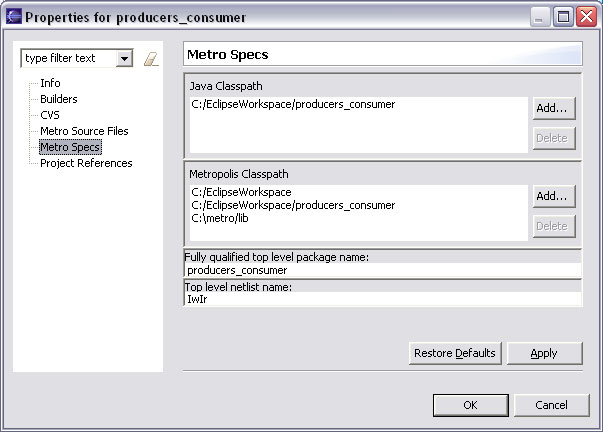
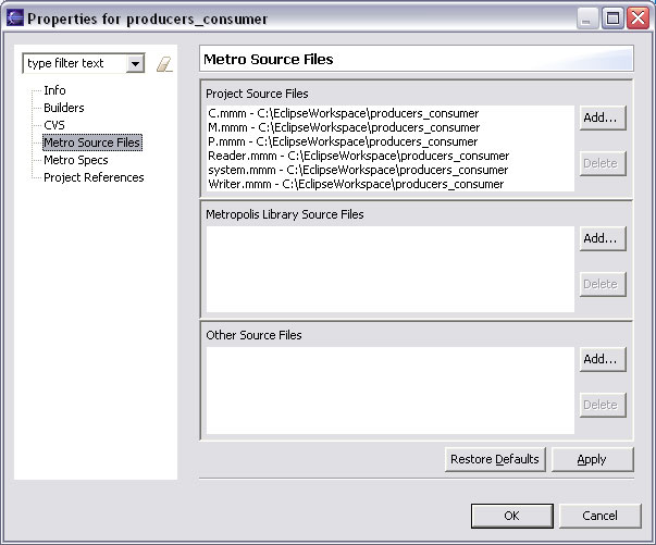
" Properties
The specifications for compiling your model
(i.e., the information you would include on the
command line of a
Metro Specs"
and "Metro Source Files".
Here are illustrations of example settings for the
producers_consumer example:
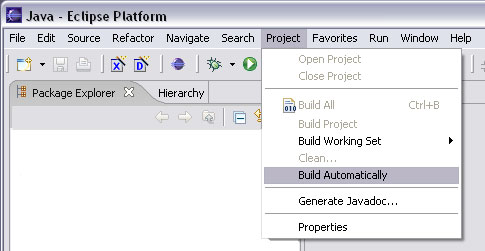
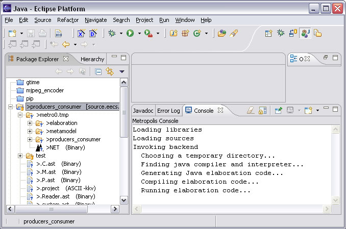
BuildingOnce your source files are in place and the properties are set correctly for compiling, you can build your model by selecting the project name, or any resource listed under it, in the Package Explorer view and then the main-menu item
Console view
(Window -> Show View -> Console)
displays the output of that process.
A successful build will create a folder inside the project called
Below is a screendump of an Eclipse window showing the output of
a successful build of the
Viewing
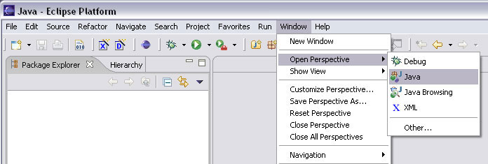
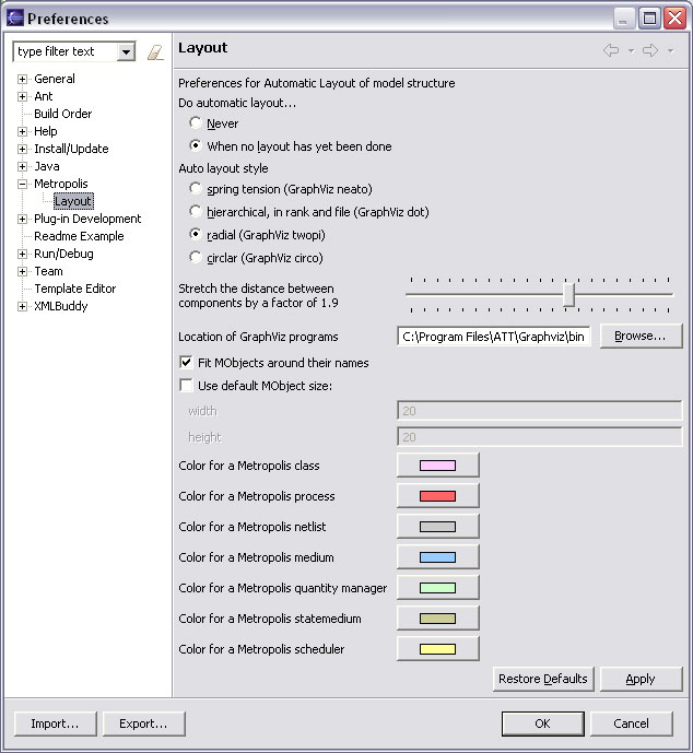
Double-clicking on the file Before describing the preferences, a note about auto-layout is in order: Automatic layout is provided as a helpful starting point for laying out a diagram. It may not provide a suitable finished layout, but can help provide an initial layout that is understandable and easily modifiable by hand. The preferences can be helpful in getting the most out of auto-layout. Layout preferencesThe layout preferences are accessed from the main Eclipse menus:
The DisplayThe display shows the structure of a netlist. The name of the netlist whose structure is being displayed appears in the tab at the top of the Structure Viewer.ComponentsThe components of the netlist appear as colored rectangles. A rectangle's color corresponds to the type of component it represents. The color key is on the layout preferences page (see above), where the colors are customizable. The name of the component in the netlist is displayed in the middle of its rectangle. Hovering over a component displays its name, the fully-qualified name of its class, and its type in a tooltip.PortsConnections between the netlist components are displayed as lines connecting them, attached at their ports. A gray circle on a component rectangle represents an input port (or interface). The name of the interface is displayed in a tooltip when the mouse hovers over it.A white circle on a component rectangle represents an output port. The name of the port is displayed in a tooltip when the mouse hovers over it. Shadow PortsA gray or white circle that is not on a component rectangle is a "shadow port". Its connection ends at a port that is not in the currently displayed netlist. Shadow ports are so called because they can be thought of as the point where a connection casts a shadow on the netlist boundary on its way to an endpoint in some other netlist.A shadow port can appear either as a free-floating symbol, when it represents a connection endpoint outside of the current netlist, or as a port symbol on a netlist object, when it represents a connection endpoint inside that netlist. The following figure illustrates: 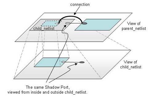
LayoutIf the preferences have been set to do automatic layout, and the GraphViz programs are correctly installed, the netlist components will be automatically layed out in some manner the first time a netlist is displayed. Automatic layout will also happen on subsequent displays of the same netlist, as long as the layout has not been saved.
The rectangular component symbols and the free-floating
shadow port symbols can be dragged into any position.
They can also be resized by selecting them and dragging their
handles.
Multiple symbols can be selected at once by dragging a selection
box around them, or by doing Saving (and a caveat)Currently, saving means saving the layout, and it is done in any of three ways described below.An important caveat: If multiple views of the model are open when one is saved -- i.e., views of multiple netlists in a hierarchical structure -- it is important to realize that the layout for all views will be saved. That is, the layout for the entire model is saved in one place and saving any view saves the layout for all views. Actions
|
| Contact |
| ©2002-2018 U.C. Regents |