


Map star is the most basic of all HOF stars. Its icon is shown below:
blockname
where_defined
parameter_map
input_map
output_map
$PTOLEMY or ~username. This lends a certain immunity to changes in the filesystem organization. Currently, the file specified must be an oct facet, although in the future, other specifications (like ptcl files) may be allowed. Usually, the oct facet simply contains the definition of the replacement galaxy. If the replacement block is a built-in star, then there is no need to give a value to the where_defined parameter.The
Map star replaces itself in the graph with as many instances of the replacement block as needed to satisfy all of the inputs to the Map star. Consider the example shown in figure
4-1.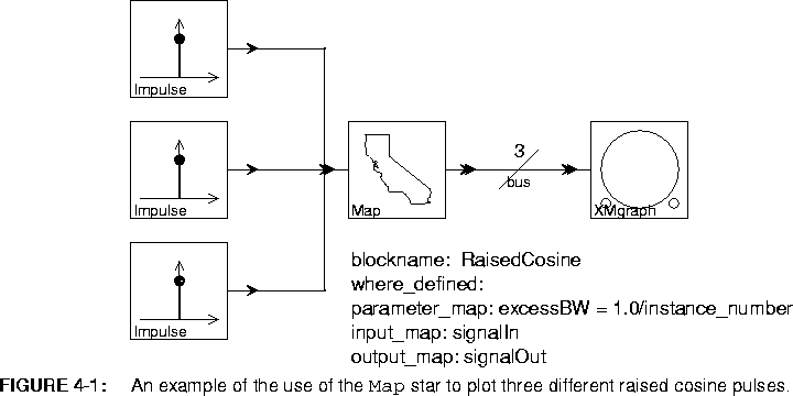
RaisedCosine star. Since this is built-in, there is no need to specify where it is defined, so the where_defined parameter is blank. The RaisedCosine star has a single input named signalIn and a single output named signalOut, so these names are given as the values of the input_map and output_map parameters. The parameter_map parameter specifies the values of the excessBW parameter for each instance of the replacement block to be created; excessBW specifies the excess bandwidth of the raised cosine pulse generated by the star. The syntax of the parameter_map parameter is discussed in detail below, but we can see that the value of the excessBW parameter will be 1.0 for the first instance of the RaisedCosine star, 0.5 for the second, and 0.33 for the third.
The horizontal slash through the last connection on the right in figure
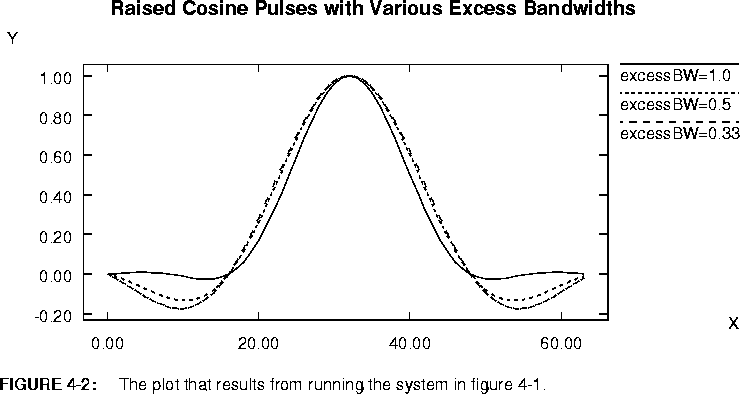
4-1 is a Bus, which is much like a delay in that the icon is placed directly over the arc without any connections. Its single parameter specifies the number of connections that the single wire represents. Here, the bus width has to be three or the Map star will issue an error message. This is because there are three inputs to the Map star, so three instances of the RaisedCosine star will be created. The three outputs from these three instances need somewhere to go. The result of running this system is shown in figure
4-2
The block diagram in figure 4-1 is equivalent to that in figure 4-3.
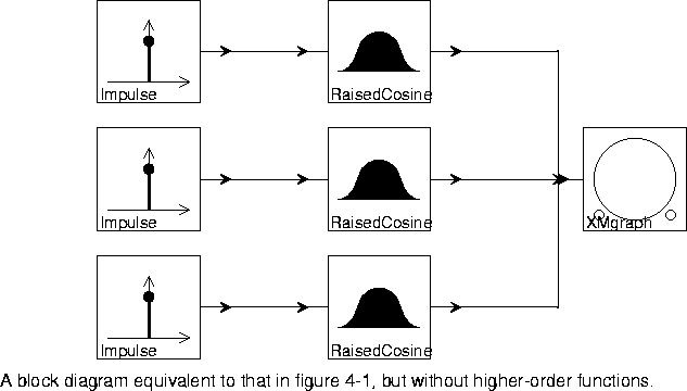
Map star has run, the topology of the Ptolemy universe will be exactly as figure
4-3. The Map star itself will not appear in the topology, so examining the topology with, for example, the ptcl print command will not show a Map star instance.
In both figures
4-1 and
4-3, the number of instances of the RaisedCosine star is specified graphically. In figure
4-1, it is specified by implication, through the number of instances of the Impulse star. In figure
4-3 it is specified directly. Neither of these really takes advantage of higher-order functions. The block diagram in figure
4-4
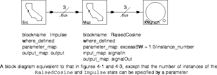
RaisedCosine star. It is only necessary to modify parameters, not the graphical representation. For example, if the value of the bus parameters in figure
4-4 were changed from 3 to 10, the system would then plot ten raised cosines instead of three.
The left-most star in figure
4-4 is a variant of the Map star called Src. It has no inputs, and its output data type is specialized to "float" (recall that ports of type "float" in Ptolemy actually communicate data of type "double" in C++). Ptolemy block diagrams are strongly typed, so any star with no inputs must have specific, well-defined types for its outputs (rather than "anytype"). There are variants of the Src higher-order star for all built-in data types in Ptolemy. The complete list of higher-order stars is given below.
Graphical versions of the Map star
Variants of the Map and Src stars, called MapGr and SrcGr, have the following icons: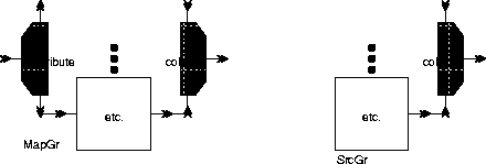
It is important to realize that MapGr and SrcGr are single icons, each representing a single star. The complicated shape of the icon is intended to be suggestive of its function when it is found in a block diagram. The MapGr and SrcGr stars work just like the Map and Src stars, except that the user specifies the replacement block graphically rather than textually. For example, the system in figure
4-4 can be specified as shown in figure
4-5.
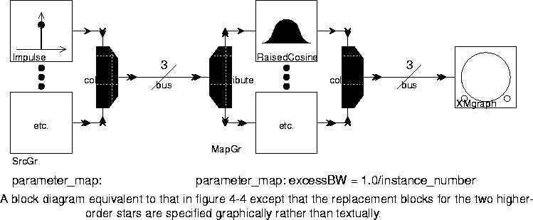
Impulse and RaisedCosine each have one instance wired into the block diagram as an example. Thus, there is no reason for the blockname, where_defined, input_map, or output_map parameters. The MapGr and SrcGr stars have only a single parameter, called parameter_map. The syntax for this parameter is the same as for the Map star, and is fully explained below.
A variant of the
MapGr star has the icon shown below: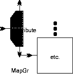
This version just represents a MapGr star with no outputs. MapGr star is shown in figure
4-6.
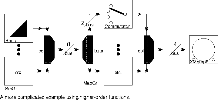
Commutator, which can take any number of inputs. The bus connected to its input multiporthole determines how many inputs will be used in each instance created by the MapGr star. In the example in figure
4-6, it is set to 2. Thus, each instance of the replacement block processes two input streams and produces one output stream. Consequently, the input bus must be twice as wide as the output bus, or the MapGr star will issue an error message. This example produces the plot shown in figure
4-7.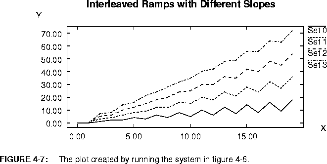
Commutator star, then the output plot will be as shown in figure
4-8.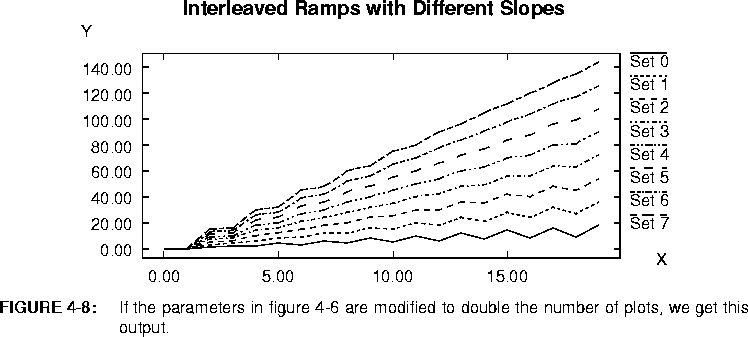
Setting parameter values
The parameter_map parameter of the Map star and related stars can be used to set parameter values in the replacement blocks. The parameter_map is a string array, a list of strings. The strings are in pairs, where the pairs are separated by spaces, and there are four acceptable forms for each pair:=, or (. In all cases, name is the name of a parameter in the replacement block. In the first and third cases, the value is applied to all instances of the replacement block. In the second and fourth cases, it is applied only to the instance specified by the instance number, (which starts with 1). The third and fourth cases just introduce an optional equal sign, for readability. If the = is used, there must be spaces around it.instance_number appears anywhere in value, it will be replaced with the instance number of the replacement block. Note that it need not be a separate token. For example, the value xxxinstance_numberyyy will become xxx1yyy for the first instance, xxx2yyy for the second, etc. After all appearances of the string instance_number have been replaced, value is evaluated using the usual Ptolemy expression evaluator for initializing String Array states.Map star has a blockname of RaisedCosine, and a parameter_map of
excessBW = 1.0/instance_numberMap star will create three instances of RaisedCosine. The first instance will have its excessBW parameter set to 1.0 (which is 1/1), the second instance of RaisedCosine will have a excessBW of 0.5 (1/2), and the third will have a excessBW of 0.33 (1/3). Since the other RaisedCosine parameters are not mentioned in the parameter_map, they are set to their default values.Map star in figure
4-1 were set to
excessBW(1) 0.6 excessBW(2) 0.5 excessBW(3) 0.4 length 128RaisedCosine would then have an excessBW of 0.6, the second would have an excessBW of 0.5 and the third would have 0.4 for its excessBW. All three of the RaisedCosine stars would have a length of 128 instead of the default length. Number of replacement blocks
The number of instances of the replacement block is determined by the number of input or output connections that have been made to the Map star. Suppose the Map star has 


How the inputs and outputs are connected
The first 
Map star will be connected to the inputs of the first instance of the replacement block. To determine in what order these 


Map star will be connected to the next replacement block, again using the ordering specified in input_map. Similarly for the outputs. If there are no inputs at all, then the number of instances is determined by the outputs, and vice versa. Substituting blocks with multiple input or output ports
When the replacement block has a multiple input port or a multiple output port (shown graphically as a double arrowhead), the name given in the input_map parameter should be the name of the multiple port, repeated for however many instances of the port are desired.Add star has a multiple input port named "input". If we want the replacement Add star(s) to have two inputs each, then input_map should be input input. If we want three inputs in each replacement block, then input_map should be input input input. Note that input_map and output_map are both of the String Array type. Thus one can use the shortcut string input[3] instead of the cumbersome input input input string. These two forms are equivalent as input[3] is converted automatically to input input input when the parameter is initialized by Ptolemy. A note about data types
In the Map star, the output data type is ANYTYPE, where the specific type will be derived from the type of the input(s). This creates a problem when there are no inputs. Thus, the zero-input version of this star is implemented as a family of derived stars called Src stars, each of which has a specific output data type.Map star, to make all type conversions explicit. Future versions of Ptolemy may implement type resolution differently, hopefully overcoming these problems. The problems do not occur with the MapGr stars, because these are able to determine the data type of the inputs and outputs from the sample replacement block, which is sure to be present when type resolution is completed. 4.2.2 Managing multidimensional data
There are many alternatives in Ptolemy for managing multidimensional data. One simple possibility is to use the MatrixParticle class. This encapsulates a matrix into a single particle. Another alternative is to use the Message class to define your own multidimensional data structure. A third alternative (which is still highly experimental) is to use the multidimensional synchronous dataflow (MDSDF) domain. A fourth alternative, discussed here, is to embed your multidimensional data into one-dimensional streams. Higher-order functions become extremely useful in this case. Our discussion will center on using the SDF domain, although the same principles could be applied in other domains as well.Distributor and a Commutator, as shown below:

FFTCx star in the SDF domain has two key parameters, the order and the size. The size is the number of input samples read each time the FFT is computed. For the row FFT, this should be equal to the number of columns. These samples are then padded with zeros (if necessary) to get a total of 2order samples. The FFTCx star then computes a 2order point FFT, producing 2order complex outputs. In figure
4-9, these outputs are then transposed so that they are column-wise rasterized. The second FFTCx star then computes the FFT of the columns. The output is column-wise rasterized.The effect of a transposition can be accomplished using higher-order functions in a way that is sometimes more intuitive. In particular, a matrix can be represented as a bus, where each connection in the bus carries one row, and the width of the bus is the number of rows. To make this concrete, the same two-dimensional FFT is re-implemented in figure 4-10
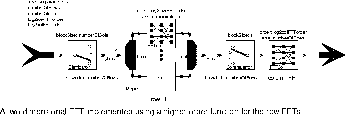
MapGr star is then used to apply the FFT to each signal in the bus. The results are recombined in column-wise rasterized format, and the column FFT is computed.
These examples are meant to illustrate the richness of possibilities for manipulating data. A more complete discussion of these issues and their application to radar signal processing are given in [Khi94].
4.2.3 Other higher-order control structures
The Map star and its variants apply instances of their replacement block in parallel to the set of input streams. Another alternative is provided by the Chain star, which strings together some specified number of instances of the replacement block in series. The parameters are similar to those of the Map star, except for the addition of internal_map. The internal_map parameter specifies connections made between successive instances of the replacement block in the cascade. It should consist of an alternating list of output and input names for the replacement block.Chain star is a string of biquad filters in series. The IIR filter star, which can be used to create a biquad filter, has an input named "signalIn" and an output named "signalOut." To have a string of these stars in series, one would want the output of the first IIR star in the series to be connected to the input of the second star. And the output of the second star should be connected to the input of the third, etc. Thus, a Chain star that is a series of biquad filters would have an internal_map ofsignalOut signalInIfElse block. This star is just like Map, except that it has two possible replacement blocks. If the condition parameter is TRUE, then the true_block is used. Otherwise, the false_block is used. It is important to realize that the condition parameter is evaluated at setup time. Once a replacement block has been selected, it cannot be changed. There are two uses for this block. It can be used to parameterize a galaxy in such a way that the parameter determines which of two functions is used within the computation. More interestingly, it can be used to implement statically-evaluated recursion.4.2.4 Statically evaluated recursion
The Map star and its variants replace themselves with an instance of the block specified as the replacement block. What if that block is a galaxy within which the very Map star in question sits? This is a recursive reference to the galaxy, but a rather awkward one. In fact, in such a configuration, the setup phase of execution will never terminate. The user has to manually abort such an execution in order to get it to terminate.IfElse star, however, can conditionally specify one of two replacement blocks. The condition parameter determines which block. One of the two replacement blocks can be a recursive reference to a galaxy as long as the condition parameter is modified. When the condition parameter changes state, going from TRUE to FALSE or FALSE to TRUE, then the choice of replacement block inside the new galaxy instance will change. This can be used to terminate the recursion.
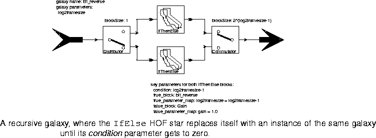
IfElse stars, each with a conditional recursive reference to the bit_reverse galaxy. The condition is log2framesize-1, and the log2framesize parameter for the inside instances of the galaxy is set to log2framesize-1. When log2framesize gets to zero, the replacement block becomes a Gain star with unity gain (which of course has no effect). This terminates the recursion.With log2framesize = 3, after the setup phase, the topology of the galaxy will have become that shown in figure 4-12.
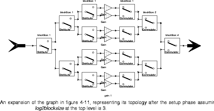
Distributors, Gains, and Commutators has no effect at all). Unfortunately, we currently have no mechanism for automatically displaying this expanded graph visually. It can, however, be examined using ptcl.
The bit_reverse galaxy performs the sort of data manipulation that is at the heart of the decimation-in-time FFT algorithm. See [Lee94] for an implementation of that algorithm using these same techniques (or see the demos).
4.2.5 Bus manipulation stars
One consequence of the introduction of higher-order functions into Ptolemy is that busses have suddenly become much more useful than they used to be. Recall that the bus icon resembles a diagonal slash, as shown in figure
4-1, and is placed over a connection, much like a delay. Its single parameter specifies the width of the bus.
Fortunately, while increasing the demand for busses, higher-order functions also provide a cost effective way to manipulate busses. Like the
Map star and its variants, the bus manipulation stars in the HOF domain modify the graph at setup time and then self-destruct. Thus, they can operate in any domain, and they introduce no run-time overhead.BusSplit star is shown in figure
4-13.
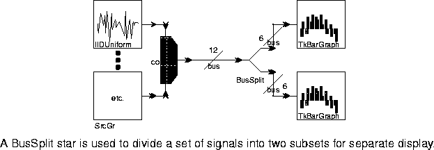
BusSplit star rewires the graph at setup time and then self-destructs. Thus, it introduces zero run-time overhead.
A more interesting bus manipulation star is the
Nop star, so called because it really performs no function at all. It can have any number of inputs, but the number of outputs must be the same as the number of inputs. All it does is connect its inputs to its outputs (at setup time) and the self-destruct. It has many icons, four of which are shown below:
The icon on the left has three individual input ports, and simply combines them into an output multiporthole. This multiporthole would normally be connected to a bus, which must be of width three. Thus, this icon provides a way to create a bus from individual connections. The next icon is similar, except that it has five input lines. The next two icons do the reverse. They are used to break out a bus into its individual components. Nop stars are shown in figure
4-14.
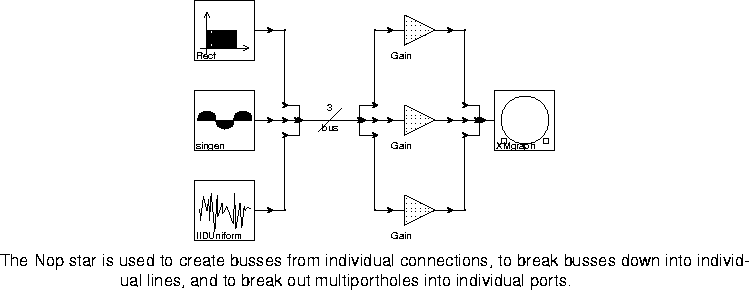
Nop star. The bus is then broken out into three individual lines, which are fed to three Gain stars. The most interesting use of the Nop star, however, is the one on the right. The XMgraph star shown there has a multiporthole input. The Nop star is simply deposited on top of the multiporthole to provide it with three individual inputs. Why do this? Because when connecting multiple signals to a multiporthole input, as done for example in figure
4-3, it is difficult to control which input line goes to which specific porthole in the multiporthole set. Putting the Nop star on the porthole gives us this control with no additional run-time cost.


Copyright © 1990-1997, University of California. All rights reserved.