[Next] [Previous] [Top]
Mapping Multiple Independent Synchronous Dataflow Graphs
In this section we present two simple applications. These examples run on a heterogeneous platform consisting of a workstation and DSP card, as described earlier. The applications are synthesized in C for the workstation, tcl/tk for the workstation graphical user interface, and Motorola 56k assembly code for the DSP card. The first example is an FM synthesis application which has five independent SDF graph components. Furthermore, the graphs that are running on the DSP are independent from the graphs running on the workstation. The second example is an acoustic modem which has two independent graphs, one of which spans over both the workstation and DSP. Thus this last example requires the use of both peek/poke and send/receive actors.
5.1 FM synthesis


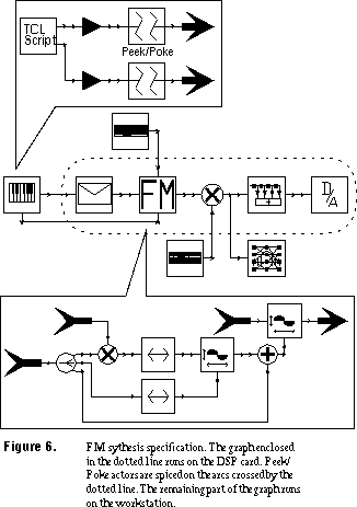
The graphical specification of the FM synthesis example is shown in figure 6
. The top-level description is shown in the middle of the figure. This application has five independent graphs, where the one that runs on the DSP is enclosed by a dotted in the figure.
The application specification is hierarchical. Two of the actors have been expanded to expose the hierarchy. All of the actors in the top-level description outside of the dotted arcs expand to graphs similar to the one at the top of the figure. Note the peek/poke actors in this graph. As their icon suggests, they provide the disconnection between the dataflow graphs; each is expanded to a peek/poke pair as shown in figure 4. The peek/poke actors disconnect the top subgraph from the subgraph that runs on the DSP. All of the other actors that run on the workstation similarly disconnect themselves from the graph running on the DSP. This allows the DSP subgraph to run as fast as necessary without synchronizing with the workstation. In this case, the sound is generated at a 32 kHz sampling rate. If we had not disconnected the graph with peek/poke actors, but rather used synchronizing send/receive actors, we would have slowed the DSP to run in lock step with the workstation, preventing the DSP from running at the required rate.
5.2 Acoustic modem


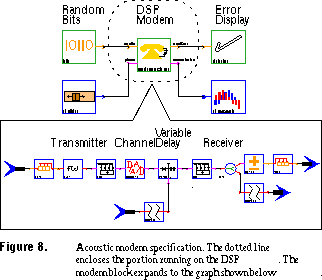
The next example, shown in figure 8
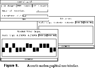
, is a simple acoustic modem. A pseudo-random sequence of bits is generated on the workstation. This sequence is sent to the DSP, which transmits and then receives the bit stream over a speaker/microphone channel. The received bits are then sent back to the workstation, where the errors are displayed to the user (see figure 9).
In this example there are two independent SDF graphs. Note that one graph spans over actors that are running on the workstation and the DSP. Peek/poke communication schemes could not be used here since we can not afford to lose bits over the channel. The other graph allows the user to adjust the phase of the incoming signal via a slider.
Mapping Multiple Independent Synchronous Dataflow Graphs
[Next] [Previous] [Top]


