


Page 16 out of 24 total pages
The continuous-time (CT) domain in Ptolemy II aims to help the design and simulation of systems that can be modeled using ordinary differential equations (ODEs). ODEs are often used to model analog circuits, plant dynamics in control systems, lumped-parameter mechanical systems, lumped-parameter heat flows and many other physical systems.
Using digital computers to simulate continuous-time systems has been studied for more than two decades. One of the most well-known tools is Spice [62]. The CT domain differs from Spice-like continuous-time simulators in two ways -- the system specification is somewhat different, and it is designed to interact with other models of computation.
We outline some basic terminology that are used in this chapter. This is not an overview of the numerical ODE solving methods, but it will help explain the operation of the domain and the motivation for its design. For a detailed understanding of ODEs and their numerical solutions, please refer to books on numerical solutions for ODEs, e.g. [26].
In general, an ODE-based continuous-time system has the following form:
where, ![]() ,
, ![]() , a real number, is continuous time. At any time t,
, a real number, is continuous time. At any time t, ![]() , an n-tuple of real numbers, is the state of the system;
, an n-tuple of real numbers, is the state of the system; ![]() is the m-dimensional input of the system;
is the m-dimensional input of the system; ![]() is the l-dimensional output of the system;
is the l-dimensional output of the system; ![]() is the derivative of
is the derivative of ![]() with respect to time
with respect to time ![]() , i.e.
, i.e.
Equations (4), (5), and (6)are called the system dynamics, the output map, and the initial condition of the system, respectively. The solution of the set of ODE is a continuous waveform x(t), which is a function of time that satisfies the equation (4) and initial condition (6). The output of the system is then defined as the function of the input that satisfies (5).
Not all ODEs have a solution, and some ODEs have more than one solution. In such situations, we say that the solution is not well defined. This is usually a result of errors in the system modeling. The following are conditions for the existence and uniqueness of solutions of ODEs. We restrict our discussion to systems that have unique solutions.
We denote by D a set in ![]() which contains at most a finite number of points per unit interval, and
which contains at most a finite number of points per unit interval, and ![]() the difference set, those points in
the difference set, those points in ![]() that are not in D. If f( ) is continuous on
that are not in D. If f( ) is continuous on ![]() , and f( ) satisfies the Lipschitz condition, then ODE (4) with the initial condition (6) has a unique solution, which is a continuous function
, and f( ) satisfies the Lipschitz condition, then ODE (4) with the initial condition (6) has a unique solution, which is a continuous function ![]() such that,
such that,
The solution is sometimes called the state trajectory of the system. By applying the output map on the state trajectory, the output of the system can be obtained.
Usually, only the solution on a finite time interval ![]() is needed. A simulation of the system is performed on discrete time points in this interval. Here we denote by
is needed. A simulation of the system is performed on discrete time points in this interval. Here we denote by
the set of the discrete time points. A "snapshot" of all the signals at ![]() is called the behavior of the system at time
is called the behavior of the system at time ![]() . To explicitly illustrate the discretization of time and the difference between the precise solution and the numerical solution, we use the following notation in the rest of the chapter:
. To explicitly illustrate the discretization of time and the difference between the precise solution and the numerical solution, we use the following notation in the rest of the chapter:
A general way of simulating a continuous-time system numerically is to compute the state and the output of the system in increasing order of ![]() . Such algorithms are called the time-marching algorithms, and, at this time, we only consider these algorithms. There are variety of numerical algorithms differ on how
. Such algorithms are called the time-marching algorithms, and, at this time, we only consider these algorithms. There are variety of numerical algorithms differ on how ![]() is computed given
is computed given ![]() . The choice of algorithm is application dependent, and usually reflects different speed and accuracy trade-offs.
. The choice of algorithm is application dependent, and usually reflects different speed and accuracy trade-offs.
One distinct characterization of the CT model is the continuity of time. This implies that a continuous-time system must have a behavior at any time of interest. The simulation engine of the CT model, although it marches discretely in time, must be able to compute the behavior of the system at any time point. The discretization of time, appearing as integration step sizes, is affected by a time point of interest (e.g. a discontinuity), by the integration error, and by the convergence in solving algebraic equations.
Time is also global, which means that all components in the system share the same notion of time.
Numerical ODE solution algorithms approximate the derivative operator in (4) using the history and the current knowledge on the state trajectory. I.e. at time ![]() , the derivative of x is approximated by
, the derivative of x is approximated by
Depending on whether ![]() explicitly appears in (13), the algorithms are called explicit integration algorithms or implicit integration algorithms. By plugging the system dynamic (4) into (12), we end up solving a set of algebraic equations in one of the two forms:
explicitly appears in (13), the algorithms are called explicit integration algorithms or implicit integration algorithms. By plugging the system dynamic (4) into (12), we end up solving a set of algebraic equations in one of the two forms:
where ![]() are derived from the time
are derived from the time ![]() , the input
, the input ![]() , the function f, and the history of x and
, the function f, and the history of x and ![]() . Solving (14) or (15) at a particular time point is called an iteration of the CT simulation.
. Solving (14) or (15) at a particular time point is called an iteration of the CT simulation.
Equation (14) can be solved simply by a function evaluation and an assignment. But the solution of (15) is the fixed point of FI( ), which may not exist, may not be unique, or may not be able to be found. The contraction mapping theorem [12] shows the existence and uniqueness of the fixed point solution, and provides one way to find it. Given the map FI ( ) is a local contraction map (generally true for small enough step sizes), let the initial guess ![]() be in the contraction radius, and then the unique fixed point can be found by iteratively computing:
be in the contraction radius, and then the unique fixed point can be found by iteratively computing:
Solving both (14) and (15) should be thought of as finding the fixed-point behavior of the system at a particular time. This means both functions ![]() should keep unchanged during one iteration of the simulation. This further implies that the topology of the system, all the parameters, and all the internal states that the firing functions depend on should maintain unchanged.
should keep unchanged during one iteration of the simulation. This further implies that the topology of the system, all the parameters, and all the internal states that the firing functions depend on should maintain unchanged.
The existence and uniqueness of the solution of an ODE (Theorem 1 in Appendix F) allows the function f to be discontinuous at a countable number of discrete points, which are called breakpoints (also called the discontinuous points in some literature). These breakpoints may be caused by the discontinuity of input signal u, or by an intrinsic property of f. In theory, the solutions at these points are not well defined. But the left and right limit are. So instead of solving the ODE at those points, we would actually try to find the left and right limit.
A breakpoint may be known beforehand, in which case it is called a predictable breakpoint (PBP). For example, a square wave source actor can tell its next flip time. This information can be used to control the discretization of time. A breakpoint can also be unpredictable (UBP), which mean it is unknown until the time it occurs. For example, an actor that varies its functionality when the input signal crosses a threshold can only report a "missed" breakpoint after an integration step is finished.
One impact of the discontinuities on the ODE solvers is that the history solutions before the discontinuous points are useless in approximating the derivative of x after the breakpoints. The solver should resolve the new initial conditions and start the solving process as if it is at the starting point.
There are usually two ways to specify a continuous time system, the conservative law model and the signal-flow model [38]. The conservative law model, also called the nodal analysis in circuit simulation [35], defines a system by its physical components, which specifies relations of cross and through variables, and the conservative laws are used to compile the component relations into global system equations. For example, in circuit simulations, the cross variables are voltages, the through variables are currents, and the conservative laws are the Kirchhoff's laws. This model directly reflects the physical components of a system, thus is easy to construct from a potential implementation. The actual mathematical form of the system is hidden. In the signal-flow model, entities in the system are maps that define the mathematical relation between the input and output signals. Entities communicate by passing signals. This model directly reflects the mathematical relations among signals, and is more convenient for specifying the systems that do not have an explicit implementation yet.
In the CT domain of Ptolemy II, the signal-flow model is chosen as the interaction semantics. The conservative law semantics may be used within an entity to define its I/O relation. There are four major reasons for this decision:
2. The signal flow model is more flexible and extensible, in the sense that it is easy to make topology changes in the problem level. For models like hybrid systems, it is more convenient to manipulate the system at this level.
3. The signal flow model is consistent with other models of computation in Ptolemy II. Most models of computation in Ptolemy use message-passing as the interaction semantics. Choosing the signal-flow model for CT makes it consistent with other domains, so the interaction of heterogeneous systems is easy to study and implement.
4. The signal flow model is compatible with the conservative law model. For physical systems that are based on conservative laws, it is usually possible to wrap them into an entity in the signal flow model. The inputs of the entity are the excitations, like the voltages on voltage sources, and the outputs are the variables that the rest of the system may be interested in.
The signal flow block diagram of the system in (4) - (6) is shown in figure 11.1 . In the figure, u,
 ![]() , x, and y, are continuous signals (waveforms) flowing from one block to the next. Since time is shared by all blocks, it is not considered an input. At any fixed time t, if the "snapshot" values x(t) and u(t) are given,
, x, and y, are continuous signals (waveforms) flowing from one block to the next. Since time is shared by all blocks, it is not considered an input. At any fixed time t, if the "snapshot" values x(t) and u(t) are given, ![]() and y(t) can be found by evaluating f( ) and g( ), which can be achieved by firing the respective blocks.
and y(t) can be found by evaluating f( ) and g( ), which can be achieved by firing the respective blocks.
Let us consider a second order linear system,
It can be written in the form of (4)-(6), if we define a vector
The system equations are, in terms of ![]() ,
,
The equations could be a model for an analog circuit as shown in figure 11.2(a)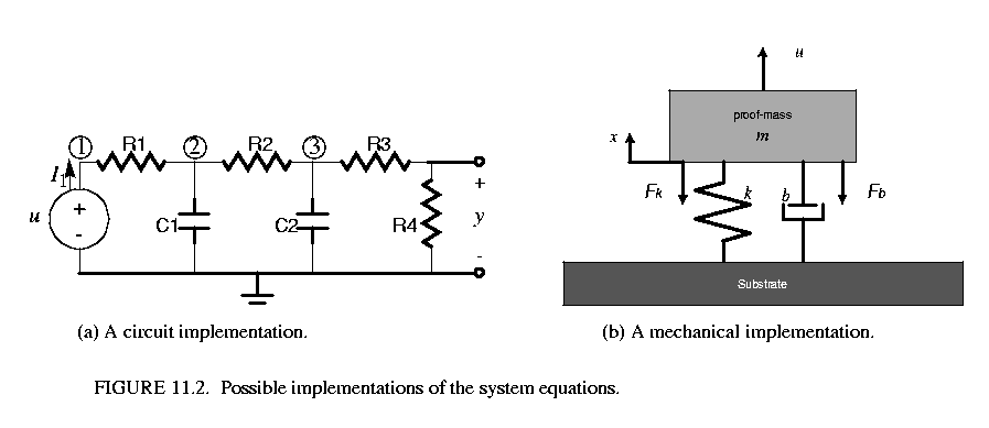 , where
Or it could be a lumped-parameter model of a spring-mass mechanical model for the system shown in figure 11.2(b), where m is the mass, k is the spring constant, b is the damping parameter, and c = 1. At the system level, we would care more about the mathematical form (17) or (19), rather than the implementation detail. The system, in the signal-flow block diagram form, is shown in figure 11.3.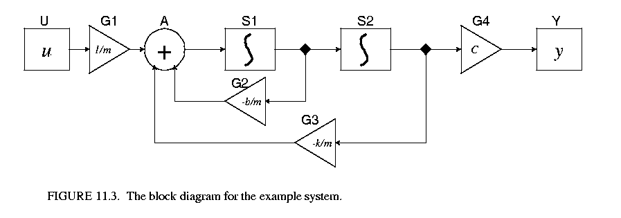 To be concrete, the conservative law model (modified nodal analysis) of the implementation figure 11.2(a) is shown in (21).
By doing some math, we can see that (21) and (19) are in fact equivalent. Equation (21) can be easily assembled from the circuit, but it is more complicated than (19). Notice that in (21) ![]() is the derivative operator, which is replace by an integration algorithm at each time step, and the system equations reduce to a set of algebraic equations. Spice software is known to have a very good simulation engine for the systems in form of (21).
is the derivative operator, which is replace by an integration algorithm at each time step, and the system equations reduce to a set of algebraic equations. Spice software is known to have a very good simulation engine for the systems in form of (21).
A CT system can be built up using actors in the ptolemy.domains.ct.lib and domain polymorphic actors that have continuous behaviors (only those implementing the SequenceActor interface need to be excluded). The central actor in CT is the integrator. It serves the unique position of wiring up ODEs. Other actors in a CT system are usually stateless. A general understanding is that all the information -- the state -- of a CT system is stored in the integrators.
In order to combine CT with other domains (which are usually discrete), some actors are designed to convert continuous signals to discrete signals (events), and vise versa. These actors are called event generators and event interpreters. Although these actors does not strictly belong to any domain, they are in the ptolemy.domains.ct.lib package. When building systems, the CT part can always provide a discrete interface to other domains.
An integrator is a single-input single-output actor, where the input is the derivative of the output (with respect to time). Since integration is not an operation that can be computed directly using digital computers, we rely on numerical integration methods to approximate it. There are a large variety of numerical integration method with different speed and accuracy trade-offs.
During the execution of a continuous-time model, the functionality of the integrators is provided by the ODE solver in charge. To ease switching ODE solvers during execution, (which is essential for handling breakpoints), the integration is delegated to the ODE solvers.
There are five ODE solvers implemented in the ptolemy.domains.ct.kernel.solver package. These solvers are ForwardEulerSolver, BackwardEulerSolver, ExplicitRK23Solver, TrapezoidalRuleSolver, and ImpulseBESolver.
In general, simulating a continuous-time system (4)-(6) by a time-marching ODE solver involves the following execution steps:
2. After the new state ![]() is computed, test whether this step is successful. Local truncation error and unpredictable breakpoints are the issues to be concerned with, those that could lead to an unsuccessful step.
is computed, test whether this step is successful. Local truncation error and unpredictable breakpoints are the issues to be concerned with, those that could lead to an unsuccessful step.
3. If the step is successful, predict the next step size. Otherwise, reduce the step size and try again.
Due to the signal-flow representation of the system, the numerical ODE solving algorithms are implemented as actor firings and token passings under proper scheduling.
The ODE solvers implemented in the CT domain include:
(3) ExplicitRK23Solver: (2(3)-order Explicit Runge-Kutta method)
with error control:
if,
, otherwise, fail. If this step is successful, the next integration step size is predicted by:
Notice that although the two time points are labeled n and n+1, they have the same (absolute) time value.
Among these solvers, (1) and (2) are fixed-step-size solvers, which do not predict step sizes according to the error tolerance; (3) and (4) are variable-step-size solvers; and (5) is a solver that specifically deals with impulses.
can be represented as in figure 11.4
An integrator is a dynamic actor that emits a token (with value equal to its internal state) at the beginning of the simulation. An integrator is a step size control actor, which can control the accuracy of the ODE solution by adjusting step sizes. An integrator has memory, its state.
To help resolving the new state, a set of variables are used:
For different ODE solving methods, the functionality of a integrator could be different. This class provide a basic implementation of the integrator, so some solver-dependent methods are delegated to the current ODE solver.
An integrator has one parameter: InitialState. At the initialization stage of the simulation, the state of the integrator is set to the initial state. The InitialState will not impact the simulation after the simulation starts. The default value of the parameter is 0. An integrator can possibly have several auxiliary variables -- _auxVariables. The _auxVariables are for the convenience of the ODE solver.
The integrator remembers the history states and their derivatives for the past several steps. The history is used for multistep methods.
2. CTPeriodicalSampler. This actor periodically samples the input signal and generates events with the value of the input signal. The sampling rate is given by parameter SamplePeriod, which has default value 0.1.
3. CTZeroCrossingDetector. This is an event detector that monitors the signal coming in from the trigger input. If the trigger is zero, then output the token from the input port. This actor controls the integration step size to accurately resolve the time that the zero crossing happens. It has a parameter ErrorTolerance, which controls how accurate the zero crossing is.
4. CTButtonEvent. This is a continuous time actor that responds to button clicks on screen. It is not an event generator. It outputs a continuous signal with value true or false. At the beginning of the execution it outputs false. If the parameter Button is changed, it will output true in the next iteration. I.e. there is, at most, one step size delay in responding to the button event. The true value will be kept for one iteration, after that the output goes back to false.
5. CTZeroOrderHold. An actor that converts events into continuous signals. This actor acts as the zero-order hold. It consumes the token when the consumeCurrentEvent() is called. This value will be held and emitted every time it is fired, until the next consumeCurrentEvent() is called. This actor has one single input port of type DoubleToken, one single output port of type DoubleToken, and no parameters.
6. CTThresholdMonitor. This actor monitors the integration steps so that the given threshold (on the input) is not crossed in one step. This actor has one input port, but no output ports. Its functionality is solely devoted to controlling the integration step size. It has two parameters ThresholdWidth and ThresholdCenter, which have default value 1e-2 and 0, respectively.
There are four CT directors -- CTSingleSolverDirector, CTMultiSolverDirector, CTMixedSignalDirector, and CTEmbeddedDirector. The first two can only serve as the top-level director, CTMixedSignalDirector can be both top-level or embedded director, and CTEmbeddedDirector can only be contained in a composite actor. In terms of mixing models of computation, all the directors can direct composite actors that implement other models of computation. Only CTMixedSignalDirector and CTEmbeddedDirector can be contained by other domains. The outside domain of a composite actor with CTMixedSignalDirector can be any discrete domain, such as DE, SDF, PN, CSP, etc. The outside domain of a composite actor with CTEmbeddedDirector can be another CT composite actor or FSM, if the outside domain of the FSM model is CT.
The CT director maintains a set of parameters which controls the simulations. The parameters shared by all CT directors are listed in Table 18 on page 11. Individual directors may have their own (additional) parameters, which will be discussed in their sections.
As the name implies, this director can only have one ODE solver, and the simulation is done using this ODE solving method. This is the simplest (and sometimes not so accurate) CT director. It is sometimes more accurate to use multiple solvers to deal with different sections of a simulation; for example, it is usually better to use another ODE solver at the breakpoints. But when the system does not have breakpoints or the user just wants a first-order approximation, this director is a lightweight choice.
This director has an additional parameter, ODESolver, as shown in Table 19 on page 12.
| Name | Description | Type | Default Value |
|---|---|---|---|
| ODESolver | The fully qualified class name for the ODE solver class. | string | ptolemy.domains.ct.kernel.solver.ForwardEulerSolver |
A CTSingleSolverDirector can direct a system that has composite actors implementing other models of computation. One simulation iteration is done in two phases: the continuous phase and the discrete phase. Let the current iteration be n. In the continuous phase, the differential equations are integrated from time ![]() to
to ![]() . After that, in the discrete phase, all (discrete) events which happen at
. After that, in the discrete phase, all (discrete) events which happen at ![]() are processed. The step size control mechanism will guarantee that no events will happen between
are processed. The step size control mechanism will guarantee that no events will happen between ![]() and
and ![]() .
.
A CTMultiSolverDirector can be considered a fancy CTSingleSolverDirector. The director can have two ODE solvers -- one for ordinary use and one specially for breakpoints. The first integration step after a breakpoint is somewhat special, since the history information is useless. Some integration methods, like high-order implicit methods, are not capable of self starting, so another (low-order) solver may be introduced to regenerate the history information.
This director has one more parameter than the CTSingleSolverDirector, as shown in Table 20 on page 12.
| Name | Description | Type | Default Value |
|---|---|---|---|
| Breakpoint-ODESolver | The fully qualified class name for the breakpoint ODE solver class. | string | ptolemy.domains.ct.kernel.solver.BackwardEulerSolver |
At the first step after the breakpoint, the integration step size is set to the minimum step size.
This director is design to be an embedded director when a CT subsystem is contained in an event-based system, like DE or DT. As proved in [51], when a CT subsystem is contained in an event-based domain, the CT subsystem should run ahead of the global time, and be ready for rollback. This director implements this optimistic execution.
Since the outside domain is event-based, each time the embedded CT subsystem is fired, the input data are events. In order to interpret the events as continuous signals, breakpoints have to be introduced. So this director extends CTMultiSolverDirector, which always has two ODE solvers. There is one more parameter used by this director -- the MaxRunAheadLength, as shown in Table 21 on page 13.
| Name | Description | Type | Default Value |
|---|---|---|---|
| MaxRunAheadLength | The maximum length of time for the CT subsystem to run ahead of the global time. | double | 1.0 |
When the CT subsystem is fired, the CTMixedSignalDirector will get the current time ![]() and the next iteration time
and the next iteration time ![]() from the outer domain, and take the min(
from the outer domain, and take the min(![]() ,
, ![]() ) as the fire end time, where
) as the fire end time, where ![]() is the value of the parameter MaxRunAheadLength. The execution is ended either when the fire end time is reached or an output event is detected.
is the value of the parameter MaxRunAheadLength. The execution is ended either when the fire end time is reached or an output event is detected.
This director supports rollback; that is when the state of the continuous subsystem is confirmed (by knowing that no events with a time earlier than the CT current time will present), the state of the system is marked. If an optimistic execution is known to be wrong, the state of the CT subsystem will roll back to the latest marked state.
This director is used when a CT subsystem is embedded in another continuous system, either directly or through a hierarchy of finite state machines. This director is typically used in the hybrid system scenario [52]. This director can pass the step size control information up to the container domain. To achieve this, the director much be contained in a CTCompositeActor, which will pass the step size control queries from the outer domain to the inner domain.
This director extends CTMultiSolverDirector, but has no additional parameters. The biggest difference of this director and the CTMixedSignalDirector is that this director does not support rollback. In fact, when CT subsystem is embedded in a continuous time environment, it does not need to rollback.
There are some demos in the CT domain showing how the domain works and the interaction with other domains.
The Lorenz System (see, for example, pp. 213-214 in [22]) is a famous nonlinear dynamic system that shows the unstable close orbit. The system is given by:
The system is built by integrators and domain polymorphic actors, as shown in figure 11.5. 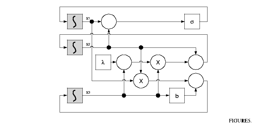
The LorenzApplet shows the chaotic attractor of the system state projected on to the ![]() plane. The initial conditions of the state variables are all 1.0. The default value of the parameters are:
plane. The initial conditions of the state variables are all 1.0. The default value of the parameters are: ![]() .
.
Micro accelerometers are MEMS devices that use beams, gaps, and electrostatics to measure acceleration. Beams and anchors, separated by gaps, form parallel plate capacitors. When the device is accelerated in the sensing direction, the displacement of the beams causes the change of the gap sizes, which further causes the change of the capacity. By measuring the change of capacity (using the capacitor bridge), the accelerate can be obtained accurately. Feedback can be applied to the beams by charging the capacitors. Using feedback can reduce the sensitivity to process variations, eliminate mechanical resonances, and increase sensor bandwidth, selectivity and dynamic range.
Sigma-delta modulation [15], also called the pulse density modulation or the bang-bang control, is a digital feedback technique, which gets the A/D conversion functionality "for free". Figure 11.6 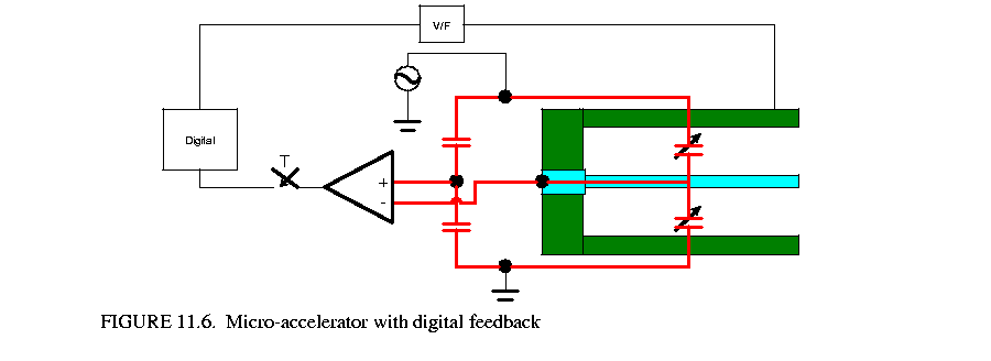 shows the conceptual diagram of system. The central part of the digital feedback is an one bit quantizer.
We implemented the system as Mark Alan Lemkin designed in [50]. As shown in the figure 11.7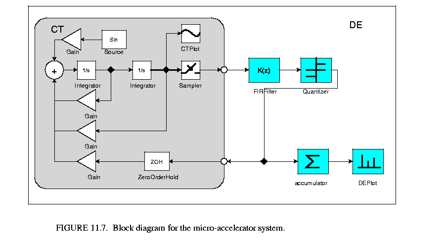 , the second order CT subsystem is used to model the beam. The voltage on the beam-gap capacitor is sampled every T seconds (much faster than the required output of the digital signal), then filtered by a lead compensator (FIR filter), and fed to an one-bit quantizer. The outputs of the quantizer are converted to force and fed back to the beams. The outputs are also counted and averaged every NT seconds to produce the digital output. In our example, the external acceleration is a sine wave.
The ThermostatApplet shows a simple thermostat system. The temperature of the room is expected to be controlled between 0 and 0.2.
The system has two states, heating and cooling, as shown in figure 11.8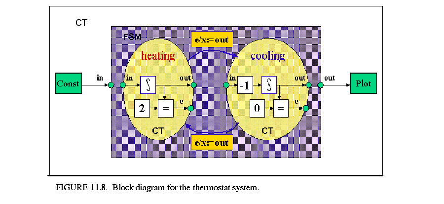 . In the heating state, the temperature of the room is increased linearly, or, in terms of a differential equation:
In the cooling state, the temperature is dropped linearly, i.e.
The control rule is that if the temperature reaches 0.2 degree, then switch the controller to the cooling state; if the temperature decreases to 0 degree then switch the controller to the heating state.
Although the system does not have very interesting dynamics, it can be used to illustrate the accuracy of detecting events, and the ability to simulate hybrid systems in Ptolemy II.
The CT domain consists of the following packages, shown in figure 11.9.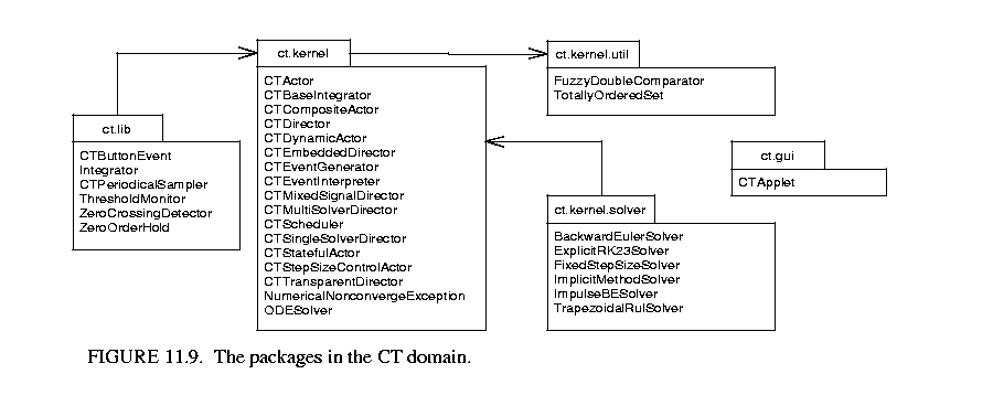
The ct.kernel.util package provides the basic data structure -- TotallyOrderedSet, which is used to implement the list to store break points. The UML for this package is shown in figure 11.10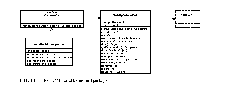 . A totally ordered set is a set (i.e. no duplicated elements), in which the elements are totally comparable. This data structure is used to store the break points since break points are processed in chronological order.
The ct.kernel package is key. It provided interfaces to classify actors. The classes, including the CTBaseIntegrator class and the ODESolver class, are shown in figure 11.11.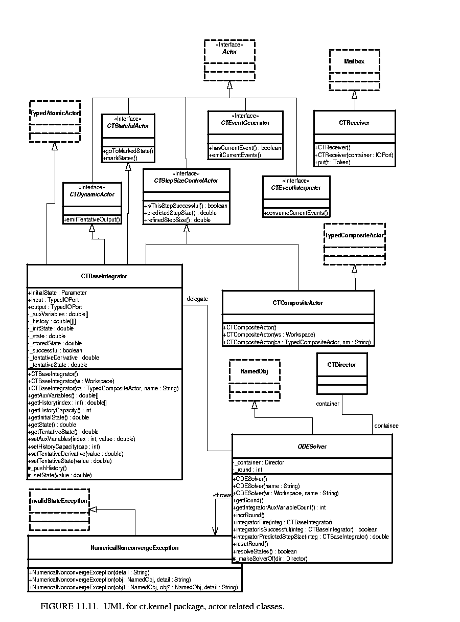
CT directors implement the semantics of the continuous time execution. These classes, including CTScheduler, are shown in figure 11.12.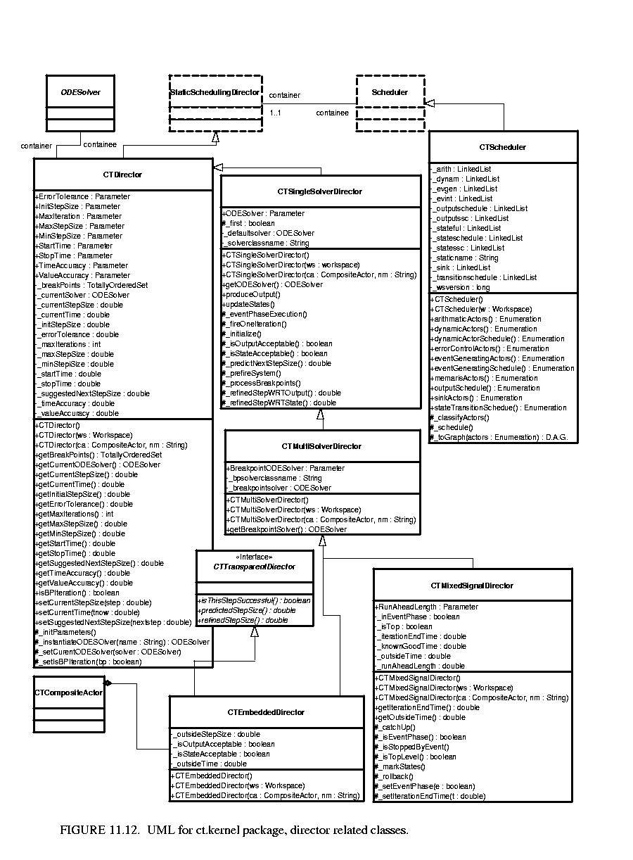
The ct.kernel.solver package provided a set of ODE solvers. The classes are shown in figure 11.13.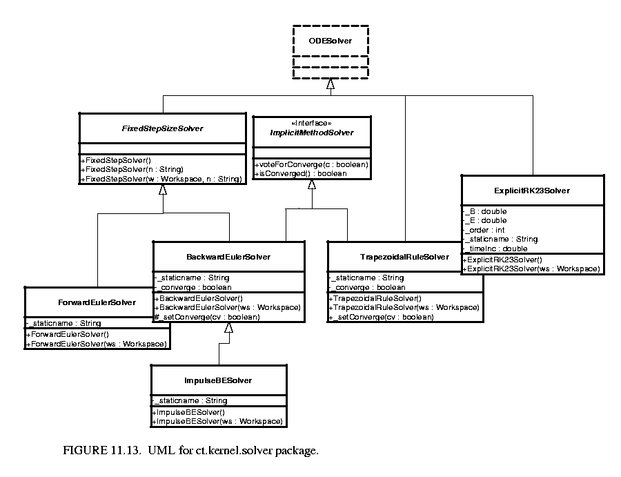
The scheduler partitions a CT system into two clusters: the state transition cluster and the output cluster. In a particular system, these clusters may overlap.
The state transition cluster includes all the actors that are in the signal flow path for evaluating the f( ) function in (4). It starts from the source actors and the outputs of the integrators, and ends at the inputs of the integrators. A topological sort of the cluster provides an enumeration of the actors in the order of their firings. This enumeration is called the state transition schedule. After the integrators produce tokens representing ![]() , one iteration of the state transition schedule gives the tokens representing
, one iteration of the state transition schedule gives the tokens representing ![]() back to the integrators.
back to the integrators.
The output cluster consists actors that are involved in the evaluation of the output map g( ) in (5). It is also similarly sorted in topological order. The output schedule starts from the source actors and the integrators, and ends at the sink actors.
For example, for the system shown in figure 11.3, the state transition schedule is
U-G1-G2-G3-A
where the order of G1, G2, and G3 are interchangeable. The output schedule is
G4-Y
The event generating schedule is empty.
A special situation that must be taken care of is the firing order of a chain of integrators, as shown in figure 11.14. For the implicit integration algorithms, the order of firings determines two distinct kinds of fixed point iterations. If the integrators are fired in the topological order, namely
 ![]() in our example, the iteration is called the Gauss-Seidel iteration. That is,
in our example, the iteration is called the Gauss-Seidel iteration. That is, ![]() always uses the new guess from
always uses the new guess from ![]() in this iteration for its new guess. On the other hand, if they are fired in the reverse topological order, the iteration is called the Gauss-Jacobi iteration, where
in this iteration for its new guess. On the other hand, if they are fired in the reverse topological order, the iteration is called the Gauss-Jacobi iteration, where ![]() uses the guess of
uses the guess of ![]() in the last iteration for its new guess. The two iterations both have their pros and cons, which are thoroughly discussed in [64]. Gauss-Seidel iteration is considered faster in the speed of convergence than Gauss-Jacobi. For explicit integration algorithms, where the new states
in the last iteration for its new guess. The two iterations both have their pros and cons, which are thoroughly discussed in [64]. Gauss-Seidel iteration is considered faster in the speed of convergence than Gauss-Jacobi. For explicit integration algorithms, where the new states ![]() are calculated solely from the history inputs up to
are calculated solely from the history inputs up to ![]() , the integrators must be fired in their reverse topological order. For simplicity, the scheduler of the CT domain, at this time, always returns the reversed topological order of a chain of integrators. This order is considered safe for all integration algorithms.
, the integrators must be fired in their reverse topological order. For simplicity, the scheduler of the CT domain, at this time, always returns the reversed topological order of a chain of integrators. This order is considered safe for all integration algorithms.
Choosing the right time points to approximate a continuous time system behavior is one of the major tasks of simulation. There are three factors that may impact the choice of the step size.
It can be shown that by carefully choosing the parameters in the integration algorithms, the local error is approximately of the p-th order of the step size, where p, an integer closely related to the number of f( ) function evaluations in one integration step, is called the order of the integration algorithm. I.e. ![]() . Therefore, in order to achieve an accurate solution, the step size should be chosen to be small. But on the other hand, small step sizes means long simulation time. In general, the choice of step size reflects the trade-off between speed and accuracy of a simulation.
. Therefore, in order to achieve an accurate solution, the step size should be chosen to be small. But on the other hand, small step sizes means long simulation time. In general, the choice of step size reflects the trade-off between speed and accuracy of a simulation.
Notice that convergence and accuracy concerns only apply to some ODE solvers. For example, explicit algorithms do not have the convergence problem, and fixed step size algorithms do not have the error control feature. On the other hand, discontinuity control is a "generic" feature that is independent on the choice of ODE solvers.
Appendix F: Brief Mathematical Background
Theorem 1. [Existence and uniqueness of the solution of an ODE
Consider the initial value ODE problem
If f satisfies the conditions:
2. [Lipschitz Condition] There is a piecewise continuous bounded function ![]() :
:![]() , where
, where ![]() is the set of non-negative real numbers, such that
is the set of non-negative real numbers, such that ![]()
Then, for each initial condition ![]() there exists a unique continuous function
there exists a unique continuous function ![]() such that,
such that,
This function ![]() is called the solution through
is called the solution through ![]() of the ODE (34).
of the ODE (34).
Theorem 2. [Contraction Mapping Theorem.
If ![]() is a local contraction map at x with contraction radius
is a local contraction map at x with contraction radius ![]() , then there exists a unique fixed point of F within the
, then there exists a unique fixed point of F within the ![]() ball centered at x. I.e. there exists a unique
ball centered at x. I.e. there exists a unique ![]() ,
, ![]() , such that
, such that ![]() . And
. And ![]() , the sequence
, the sequence